1. Introduction, Features and Applications
Introduction
The MA860H is a high performance microstepping driver based on pure-sinusoidal currentcontrol technology. Owing to the above technology and the self-adjustment technology (self-adjust current control parameters) according to different motors, the driven motors can run with smaller noise, lower heating, smoother movement and have better performances at higher speed than most of the drivers in the markets. It is suitable for driving 2-phase and 4-phase hybrid stepping motors.
Features
l High performance, cost-effective
l Supply voltage up to 80VAC or +110VDC
l Output current up to 7.2A
l Self-adjustment technology
l Pure-sinusoidal current control technology
l Pulse input frequency up to 300 KHz
l TTL compatible and optically isolated input
l Automatic idle-current reduction
l 16 selectable resolutions in decimal and binary, up to 51,200 steps/rev
l Suitable for 2-phase and 4-phase motors
l Support PUL/DIR and CW/CCW modes
l Short-voltage, over-voltage, over-current and short-cicuit protection
Applications
Suitable for a wide range of stepping motors, from NEMA size 17 to 43. It can be used in various kinds of machines, such as X-Y tables, labeling machines, laser cutters, engraving machines, pick-place devices, and so on. Particularly adapt to the applications desired with low noise, low heating, high speed performance.
2. Specifications
Electrical Specifications (Tj = 25Ōäā/77Ōäē)
|
Parameters |
MA860H |
|
Min |
Typical |
Max |
Unit |
|
Output current |
2.6 |
- |
7.2(5.1RMS) |
A |
|
Supply voltage |
18 |
60 |
80 |
VAC |
|
+24 |
+80 |
+110 |
VDC |
|
Logic signal current |
7 |
10 |
16 |
mA |
|
Pulse input frequency |
0 |
- |
300 |
KHz |
|
Isolation resistance |
500 |
|
|
MΩ |
Operating Environment and other Specifications
|
Cooling |
Natural Cooling or Forced cooling |
|
Operating Environment |
Environment |
Avoid dust, oil fog and corrosive gases |
|
Ambient Temperature |
0 Ōäā’╝Ź 50Ōäā (32Ōäē ’╝Ź 122Ōäē) |
|
Humidity |
40%RH ’╝Ź 90%RH |
|
Operating Temperature |
70Ōäā (158Ōäē) Max |
|
Vibration |
5.9m/s2 Max |
|
Storage Temperature |
-20 Ōäā ’╝Ź 65Ōäā (-4Ōäē ’╝Ź 149Ōäē) |
|
Weight |
Approx. 650g |
Mechanical Specifications (unit: mm)
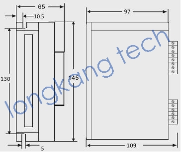
Figure 1: Mechanical specifications
*Recommend use side mounting for better heat dissipationElimination of Heat
l Driver’s reliable working temperature should be <70Ōäā(158Ōäē), and motor working temperature should be <80Ōäā(176Ōäē);
l It is recommended to use automatic idle-current mode, namely current automatically reduce to 60% when motor stops, so as to reduce driver heating and motor heating;
l It is recommended to mount the driver vertically to maximize heat sink area. Use forced coolingmethod to cool the system if necessary.
3. Pin Assignment and Description
The MA860H has two connectors, connector P1 for control signals connections, and connector P2 for power and motor connections. The following tables are brief descriptions of the two connectors. More detailed descriptions of the pins and related issues are presented in section 4, 5, 9.
Connector P1 Configuration
|
Pin Function |
Details |
|
PUL+ |
Pulsesignal: In single pulse (pulse/direction) mode, this input represents pulsesignal; 4-5Vwhen PUL-HIGH, 0-0.5V when PUL-LOW. In double pulse mode(pulse/pulse) , this input represents clockwise (CW) pulse’╝īactive at high levelor lowlevel (set by inside jumper J1 & J2). For reliable response, pulse widthshould be longer than 1.5μs. Series connect resistors for current-limiting when+12V or +24V used. The same as DIR and ENA signals. |
|
PUL- |
|
DIR+ |
DIRsignal: In single-pulse mode, this signal has low/high voltage levels,representing two directions of motor rotation; in double-pulse mode (set byinside jumper J1& J2), this signal is counter-clock (CCW) puls. For reliable motion response, DIRsignal should be ahead of PUL signal by 5μs at least. 4-5V when DIR-HIGH,0-0.5V when DIR-LOW. Please note that motion direction is also related tomotor-driver wiring match. Exchanging the connection of two wires for a coilto the driver will reverse motion direction. |
|
DIR- |
|
ENA+ |
Enablesignal: This signal is used for enabling/disabling the driver. High level(NPN control signal, PNP and Differential control signals are on the contrary,namely Low level for enabling.) for enabling the driver and low level fordisabling the driver. Usually left UNCONNECTED (ENABLED) |
Selecting Control Signal Mode and Motor Decay Mode
There are two jumpers J1 and J2 inside the MA860H specifically for selecting control signal mode, as shown in figure 2. Default setting is PUL/DIR mode.
There are two jumpers J1 and J2 inside the MA860H specifically for selecting motor decay mode, as shown in figure 2. Default setting is AUTO-DECAY mode
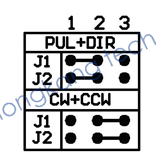
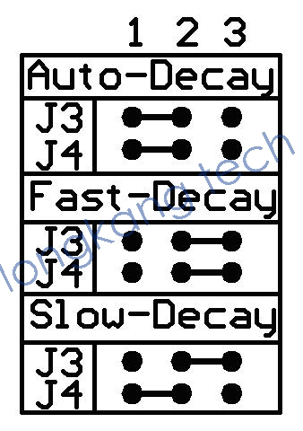
Figure 2: J1 J2 J3 and J4 jumpers
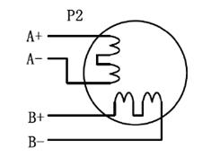
Connector P2 Configurations
|
Pin Function |
Details |
|
DC+ |
Power supply, 18~80 VAC or 24~110 VDC, Including voltage fluctuation
and EMF voltage. Recommended 18~60VAC or 24~85VDC |
|
DC- |
|
A+, A- |
Motor Phase A |
|
B+, B- |
Motor Phase B |
4. Control Signal Connector (P1) Interface
The MA860H can accept differential and single-ended inputs (including open-collector and PNP output). The MA860H has 3 optically isolated logic inputs which are located on connector P1 to accept line driver control signals. These inputs are isolated to minimize or eliminate electrical noises coupled onto the drive control signals. Recommend use line driver control signals to increase noise immunity of the driver in interference environments. In the following figures, connections to open-collector and PNP signals are illustrated.
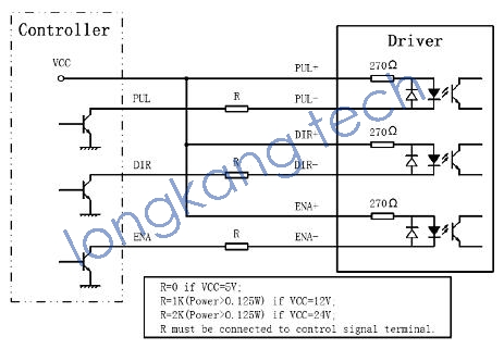
Figure 3: Connections to open-collector signal (common-anode)
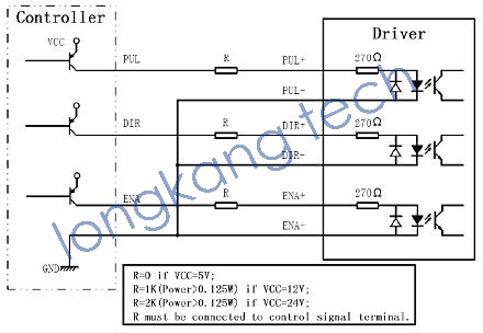
Figure 4: Connection to PNP signal (common-cathode)
5. Connecting the Motor
The MA860H can drive any 2-pahse and 4-pahse hybrid stepping motors.
Connections to 4-lead Motors
4 lead motors are the least flexible but easiest to wire. Speed and torque will depend on winding inductance. In setting the driver output current, multiply the specified phase current by 1.4 todetermine the peak output current.